Details
Type: Operational Notice
Topic or Program: Motor Carrier
Final Number: MCTD-01
Effective Date: 11/07/2016
Signature on File:
Amy Ramsdell, ODOT MCTD Division Administrator;
Tom Lauer, ODOT Chief Highway Engineer
Purpose
The purpose of this document is to establish guidelines for engineering requirements relating to Motor Carrier Transportation Division projects throughout the state. The purpose of this guidance is to ensure compliance with ODOT Policy # DES 05-02 which is in place to safeguard life, health, and property.
Background
In 2010 Oregon Department of Transportation began reviewing our policies and procedures regarding requirements by ORS 672 and professionals of record. ODOT’s Chief Highway Engineer has the responsibility and authority to issue and approve department policies and procedures for professional of record requirements consistent with governing statutes, rules, and decisions of the applicable professional boards.
This notice provides guidance so ODOT Motor Carrier Transportation Division can determine professional of record needs and requirements during construction projects, maintenance activities and maintenance projects.
Definitions
- Professional of Record (POR)
- Includes all licensed professionals that, by the conditions of their professional license, can legally produce final work or work products requiring a professional license.
Guidance for Motor Carrier Crews and Projects
ODOT Standard Drawings: Standard Drawings or Specifications can only be used to fulfill requirements of a Licensed Professional when all of the following criteria are met:
- Document has been engineered and stamped by a licensed professional
- Oregon Department of Transportation retains a valid copy of the document on file
- Drawings or specifications contain adequate information and specifications for a non-engineer to perform the preparation and application of materials used so that engineering skills are not required.
Oregon Temporary Traffic Control Handbook (OTTCH): The Oregon Temporary Traffic Control Handbook can be applied, if applicable, during maintenance activities and District Permitting Operations according to the following:
- The standards in the OTTCH were developed in a cooperative effort with ODOT, the Oregon Traffic Control Devices Committee, and subcommittees from local and state public works and maintenance jurisdictions. The standards were adopted by the Oregon Transportation Commission as the standards for all temporary traffic control in place continuously for three days or less on Oregon public roads per their designated authority in ORS 810.200 and OAR 734-020-0005.
- For work not applicable to the OTTCH or work requiring devices in place longer than three continuous days, a more comprehensive Traffic Control Plan (TCP) is needed and a licensed professional may be required.
Requirements Regarding Licensed Professionals
MAINTENANCE REPAIR DRAWINGS, PLANS, SPECIFICATIONS, SPECIAL PROVISIONS, OR CALCULATIONS REQUIRE A LICENSED PROFESSIONAL FOR THE FOLLOWING:
Pavement
- New pavement construction, reconstruction, or overlays more than 2” thick, or other non-localized repairs intended to increase structural capacity to existing pavement that has suffered major deterioration.
Geotechnical/Geology
- Retaining Walls: New construction or structural repairs to retaining walls greater than 4 feet high measured from the base of the footing to the top of the wall and any wall with a surcharge load1.
- New construction or structural repairs to sound walls
- New construction or structural repairs to poles, masts, and towers.
- Structure foundations for bridges, viaducts, pumping stations, sound walls, buildings, large culverts, etc
- New construction or non-localized repair when steepening a slope that is greater than 4 feet in height.
Definitions:
1 - A surcharge load is any load in addition to a 1V:4H slope at the top of the wall and within the area defined by the distance “H” from the top of the wall. Examples may include a structure, building, driveway, fill material, etc. (See Minor Wall Diagram)
2 – The footing is measured from the base of the footing to the top of the wall. (See Minor Wall Diagram for H< = 4.0’)
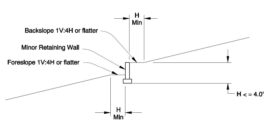 Minor Wall Diagram
Hydraulics
- Modification of storm water control features
- Structural design of culverts, and arches including headwalls, wing walls, vaults, and other man-made items
- Culvert replacement where fish passage is a concern
- Culvert replacement with a diameter or width greater than 4 feet
- Pipe replacement with a trench deeper than 5 feet without either a pre-engineered trench protective system or a back slope of 1V:1 ½ H or flatter unless a sloping design can be applied using tabulated data such as tables and charts pre-approved by an engineer that includes criteria to enable the user to make a selection and know the limits of the data
- Pipe replacement requiring a trench 20 feet deep or greater
Traffic & Roadway Services
Striping/Legends:
- Major reconstruction or major lane modification that changes the intent of the design
- New legend installations except those supplemental additions to improve the existing feature (i.e. supplemental bike lane symbols)
Signs and Sign Supports:
- New permanent sign installation or removal of signs1
- Structural design of new permanent sign supports2
Signals:
- Traffic signal operations design elements report
- Traffic signal plans and installations
- Permanent Traffic Signal Timing Deviations – Deviations from ODOT TSP&G, MUTCD should and shall conditions, and STE/RTE operational approvals
- Wiring diagrams
- New installation of flashing beacons
Illumination:
- New illumination installation, plans, and calculations
- Removal of illumination
- Changing the type of illumination heads
- Structural modification to luminaire poles
Intelligent Transportation Systems (ITS):
- ITS construction plans and calculations
- Structural modifications to ITS features
Roadway:
- New guardrail installation that changes the existing location
- Permanent removal of guardrail
- Travel lane additions or modifications
- Roadway geometry changes
Definitions:
1 – Sign – The rigid substrate (aluminum or plywood) and the legend and symbols affixed to the substrate.
2 – Sign Support – Includes the supporting elements for a sign (i.e. post, foundation, and connections.