Described in the following pages are:
- O&M CAD and Drafting standards, their use and location.
- Basic instructions for the set up and completion of a stormwater facility operational plan
- Example drawings
- A drawing check list
All of the O&M CAD standards are located in a cell library named OandM.cel, and in a seed file named seed_OM.dgn. These standards files are contained in ODOT’s Engineering workspace and are available to all ODOT MicroStation users. The workspace is available to consultants as a download on
ODOT’s website.
Cell Library
The cell library, OandM.cel file, contains individual cell drawings that are used on stormwater facility O&M operational plan sheets. These cell drawings include:
- Standard text items
- Symbols specific to stormwater facility operational plans
- Several common facility details, (i.e. manholes, inlets, cleanouts)
The details can be modified to match design or as-constructed information for individual projects. Facility details imported from final construction plans may also be used as long as construction information is deleted and replaced with operational information as directed by the EOR.
Task Dialog
The OM Operational Plan task tools are located in the engineering workspace as a workflow within the main Geo Hyd Env task tab. The cell libraries are accessed for the discipline specific tasks.
Seed File
The seed file (Seed_OM.dgn) is located with other seed files in the ODOT workspace. Seed files are accessed in the “new” drawing dialog. After naming the new file, the user browses to the preferred seed and then saves the drawing.
The new drawing will open with the seed in place. The Seed_OM.dgn file contains a ready-made blank plan sheet (or template), which includes a standard sheet border and titleblock for operational plans.
This working seed/template contains standard elements used in every O&M operational plan.
- A standard 11”X17” sheet border
- A standard O&M titleblock
- Operational plan drawing content “cache”, for layout guidance and element matching
- Example isometric pipe schematic
- Standard O&M notes and drawing legend.
- Notes to drafter
The “Notes to drafter” describe file naming conventions, location of example operational plans, and a check list of drawing items to be included on each operational plan.
“Notes to drafter” are construction elements located outside the sheet border and will not print.
At drawing completion, and prior to submittal, all items located outside the sheet border, are to be deleted. This action clears the file of unnecessary data and reduces the file size making it more manageable to the end user.
See Appendix B for a link to the seed_OM.dgn file.
Levels
When importing the facility design from the contract plans file, turn off all unnecessary levels; see the “Base Map Setup” portion of this bulletin for a list of elements to retain.
Within the seed file, two levels are typically used for operational plan elements; Level P_HY_FEAT_GENERAL is used for detail line work. Level P_HY_FEAT_GENERALTX is used for text, dimension lines, section lines, leader and flow lines, and pipe and structure location labels. Use these two levels as much as possible for consistency.
Retain original element levels in files referenced into the operational plan.
These operational plan sheets are a general graphic representation of the type, size and location of the facility and will not be used for any other purpose than as part of a facility maintenance and operations manual; therefore the levels do not carry the same importance as in construction plans.
Sheet Number Conventions
Because some operational plans contain only 1 sheet, and others contain 2 or more sheets, numbering the first sheet of a multi sheet set with 1 of 1, or 1 of 2 and the second sheet with 2 of 2, (and so on), is essential. The purpose of this type of sheet designation is to inform maintenance personnel of the number of plan sheets to expect for a particular facility. This number is in the seed file and located near the titleblock above the “By:” names.
File Naming Conventions
ODOT’s “Document Naming” tool in ProjectWise is the only approved method for naming project documents, including these OM operational plans. Using the tool is required to maintain naming accuracy and consistency. File naming is organized by disciplines using origin ID’s specific to each discipline. Project Key Numbers are included in the names, as are specifics related to the content of each document. File names for O&M “Operational Plans” include an assigned DFI number, per facility per project. Contact the Engineer of record for the DFI number assigned to the facility.
The ProjectWise website contains more information on the practices and procedures for working in ProjectWise. Links to training and other user documents are included.
Internal users: http://transnet.odot.state.or.us/hwy/projectwise/SitePages/Home.aspx
External users:http://www.oregon.gov/ODOT/Business/Pages/ProjectWise.aspx
For assistance, contact the ProjectWise Support desk at:
ProjectWiseAdmin@odot.state.or.us or call 503.986.3190.
Example Drawings
See Appendix A of this bulletin for example operational plans, plus a link to more example plan sheets provided on the
Geo-Environmental Drafting webpage. Appendix A contains three different facility types with plans, cross sections, isometric pipe schematics and details. Cross sections/profiles are generally used for pond and swale type facilities, and isometric schematics are used for complex drainage pipe and structure type facilities.
Refer to chapter 14 of the Hydraulics Manual for more information regarding facility types.
Sheet Development
Described here are the necessary steps to creating a new operational plan.
- Start a new drawing using seed_OM.dgn as a template. Fill in the titleblock with the correct information for the operational plan.
Create a base map plan view of the facility. This can be done in one of several different ways.
Method 1 - Draw the facility line work from a sketch.
Method 2 - Trace the facility line work from an imported PDF
Method 3 - Reference in the contract plans design file for the road and stormwater/drainage designs for the facility.
- Turn off unnecessary levels and/or delete any line work not needed. (See the plan elements to retain list under Base Map setup).
- Place the plan view in the top left area of the plan sheet.
- Scale the plan view up or down as needed to provide readability and to fill the top left area of the sheet, leaving room in the top right area for cross sections/details
- Create a profile/section of the facility, or if available add them from the contract plans file. As space allows, place the profile just below the plan view and align with components on the plan view.
- For facilities containing a complex system of drainage pipes/facilities, provide an isometric drainage pipe schematic in place of a profile
- Place cross sections/details on the right side of the sheet, to the right of the plan view. If needed, use a second sheet, for multiple sections/details.
- Add elements and linestyles, such as a legend, facility component labels, pipe sizes, gates, access points, Primary system pipe, patterns, etc., using the task tools.
- Refer to the project EOR for appropriate facility component labels per facility type.
- If needed, use the cache in the seed file to match element settings.
- Use the check list in the “Notes to Drafter” to assure all items have been included on the plan.
O&M specific elements to be included on each operational plan:
- Numbered Callouts for facility components, (see
Hydraulics Guidance Materials for component lists in the Standard Operation Manuals pdf’s)
- Primary and adjacent facility DFI labels
- Mile Point label
- Drawing title
- Highway and Street names
- Flow arrows (drainage flow direction, road surface sheet flow and traffic flow direction)
- Symbols (i.e. manholes, inlets, etc.)
- Custom lines (Primary System Pipe)
- Features (i.e. Fence, gates, facility access, riprap, etc.)
- Legend
Also refer to the example drawings in Appendix A, and to the drawing check list in the “Notes to Drafter” in the seed file, for items to be included.
When creating an operational plan for a backlogged facility that has been built and is in use, locating the original contract plans (.dgn’s) can be done by locating the construction as-built PDF documents in FileNet/ProjectWise. (See the Stormwater “Operation & Maintenance Manuals Workflow Procedures and Core Tasks” guidance for more information and a link to “FileNet”).
For projects completed prior to ODOT’s use of ProjectWise, use the Key number and County name information found on the as-built plans, to locate the original DGN files:
Internal users: Engineering Archives
External users: Contact the Senior Hydraulics Engineer to request the files.
Reference in the original DGN file, and follow the sheet development steps previously described. To eliminate having reference files attached to the operational plan, copy the line work into the file and detach the references. Proceed with turning off unnecessary levels, and delete line work that is not needed.
When the original DGN files are not available, a PDF of the facility plan can be imported into the MicroStation file and all necessary lines can be traced to create a plan view of the facility. When the line work is completed, delete the PDF from the drawing file.
For positioning of drawing elements, refer to the example operational plans in the appendices of this bulletin.
Base Map Setup
(When using a referenced contract plans design file for line work, do not include construction notes or labels).
To create a
plan view base map of a facility for an O&M operational plan, retain/draw the following elements.
List of plan elements to be included on the plan view:
- Edge of Pavement or gravel
- Any side streets near facility
- Adjacent sidewalks and curbs
- Adjacent traffic features (i.e. barriers, signs, bridges, walls, etc.)
- Facility access points (roads, gates, etc.)
- Facility (Pond, swale, structure, etc.)
- Drainage piping in and out of the facility
- Manholes and Inlets (upstream and downstream)
- Median lines (if necessary to clarify the drawing)
- Ditches
- Flow Directions (conveyance, drainage and traffic)
- North Arrow
Refer to the example drawings in the appendices, and the drawing check list in the seed file for items to include.
The intent of an operational plan is to provide maintenance personnel with a simple graphic representation of the constructed components of a facility. The inclusion of surrounding roadside elements and other nearby facilities on the plans aids personnel in locating and accessing each facility on the ground. Drafters are to work closely with the design engineer in determining what elements are necessary for the purpose of providing these operational plans. The design engineer will specify which elements are primary to the facility, and which are secondary. The drafter will assign the correct linestyle and line weight to the primary elements and secondary elements, as shown in the example drawings.
Primary elements of a facility, such as the pond top of slope shown in Figure 1 and the pipes flowing into and out of the pond, are shown using a line weight of 3. The line work of primary pipes are a custom linestyle located in the tasks menu. The idea is to have all the lines pertinent to the primary facility display bolder than all other lines. Labeling of the primary components is directed by the designer/EOR and is shown by placing the corresponding bubble component label from the task menu or cell library.
Secondary elements and line work remain as-is from the design file, or drawn at a weight of 1. Secondary elements are those items considered not a part of the primary facility, though some may be connected to it in some way (e.g. the surrounding drainage pipes) and also may be part of a neighboring facility. See the design engineer for determination of primary verses secondary elements for each facility. Secondary elements are not given component labels. Refer to the example drawings and the OM Stormwater task tab to obtain the correct symbols for primary and secondary elements, such as manholes and inlets.
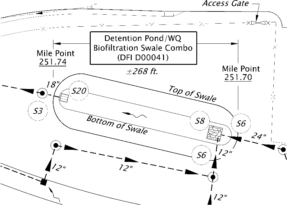
Figure 1: Pond/Swale Facility
In this example the bottom of slope is shown as a solid line with a weight of 1, similar to secondary elements, for the purpose of clarity and readability in a small space).
Profile View
The
profile view is generally shown along the center line of the facility and running the length of the overall facility. The project designer/EOR will determine the length of the profile. For example; the profile of the pond in Figure 1 above, may need to include the manhole labeled S3, but not the manhole near the other end.
The profile view is placed directly below the plan view on the sheet. Profiles include the following:
- All drainage running into or out of the facility.
- Components connected to the drainage, or contained within the facility.
- Align the facility components in the profile view with the same components shown above it in the plan view whenever possible.
- When necessary scale up the profile to clearly show the sizes and locations of multiple components.
- Label all components of the facility with the appropriate component bubble labels provided in the tasks menu.
- Label all other parts of the facility and surrounding features with standard text and leader labels.
Coordination is essential to determining which components/features are included in the profile, and which component labels to use for each component/feature.
Profiles must be clear and readable for maintenance personnel to determine which components need their attention. All the major parts of the facility must be labeled and graphically readable. When the length of a facility causes the profile to appear too small for clarity, use one or both of the following options to clearly show the facility components and their parts.
- Expand the Horizontal/Vertical scale of the profile.
- Use supplemental sections, cross-sections and/or details.
Figure 2: Profile Biofiltration Swale
Complex drainage pipe systems may require a schematic view rather than a profile or section view. When providing a drainage pipe schematic use correct isometric drafting techniques, including correct angles, to clearly demonstrate the relationships of the parts, one to another. An isometric view shows exactly what type of components are included, the pipe connections from component to component, and the direction of flow. Providing this type of graphic representation assists maintenance personnel in locating the individual components necessary to complete their maintenance work. Isometric components and pipe sections are located in the cell library. For a visual see
Figure 3: Drainage Pipe System Schematic.
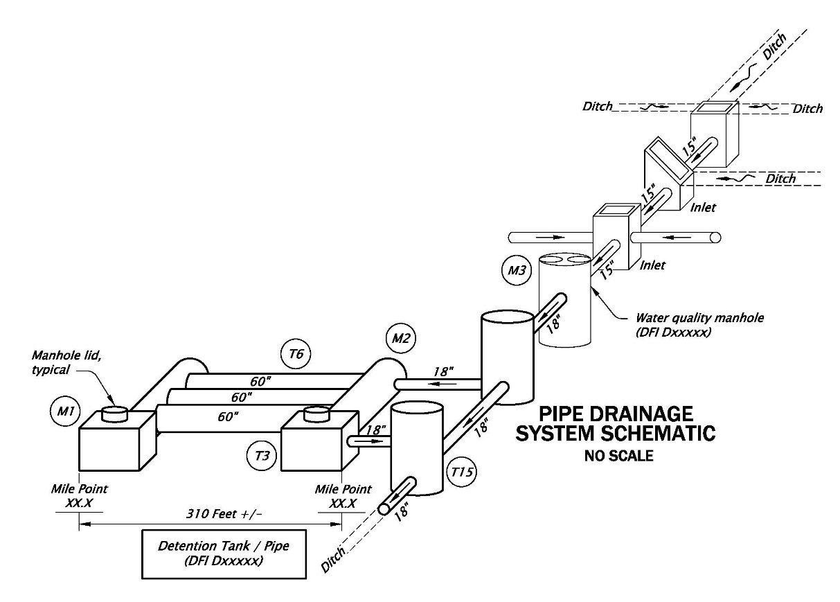
Figure 3: Drainage Pipe System Schematic
Details, cross sections and a legend are placed in the right side portion of the plan sheet. Generally the legend appears directly above the titleblock area. Cross sections and/or other details are placed directly above the legend in a manner to fill the white space of the right side of the plan sheet.
When a detail includes a cross section, place each piece next to each other with the cross section either directly to the right or directly below the corresponding detail, as shown in
Figure 4.
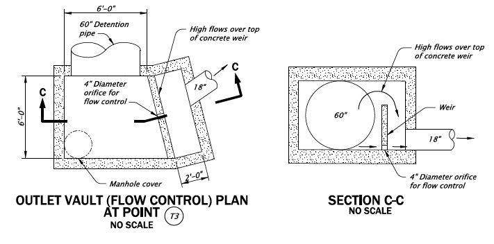
Figure 4: Outlet Vault Detail with Cross Section
Common drafting practice is preferred in sheet layout, but at times the amount of usable space on the sheet requires an unconventional layout of the elements. The designer/ERO and the drafter work together to provide the best solution for these instances. Occasionally a second sheet is warranted, but should be avoided whenever possible.
Refer to the example drawings for layout options.
Summary of Drafting Tasks to Completion
In preparing a completed O&M operational plan drawing for review by the design engineer, perform the following.
- Fill in the title block, (refer to the example plans, and also the Hydraulics Manual, Chapter 4).
- Draft a plan view of the facility.
- Draft a profile/section, plus cross section/s
- If applicable, draw an isometric pipe schematic in place of the profile/section.
- Include applicable details (use a second sheet if necessary).
- Include a North arrow.
- Include a legend.
- Delete everything outside the sheet border.
- Create a final PDF.
Final Plan Check
A check list of the items to include on each operational plan is located in the seed file with the “Notes to Drafter”. When the plan is complete and all items have been checked, delete the check list from the file along with all other items located around the outside of the sheet border and create a PDF.
Submit/Distribute
Submit the electronic DGN file and a PDF file of the final operational plan to the designer/EOR for each Stormwater facility O&M manual. The operational plan is included in the O&M manual.
The operational plan files, and a copy of the O&M Manual are submitted to ODOT’s Senior Hydraulic Engineer, located in the GES Section of Technical Services. The Senior Hydraulic Engineer will publish them to ODOT’s TransGIS where maintenance personnel have access to them.